SEWERAGE TREATMENT MODULE --
CA-12 and and CA-15
Description & Technical Specifications
Model CA-25
Models CA-30
Similar to the CA-12 and CA-15, the CA-25 operates most efficiently when used on residential applications ranging from 1,500 – 2,000 GPD. With a peak flow capacity of 2,500 GPD, the CA-25 may be applicable for small clustered development projects or in some small flow commercial/institutional flows.
Due to increased demand by design engineers for sludge management, Cromaglass developed the CA-30 with sludge wasting capabilities. This provides the operator a tool to optimize the activated sludge process. With redundancy in aeration and discharge, the CA-30 was the first complete fail-safe batch reactor. The CA-30 comes standard with built-in automation for responding to fluctuations in order to satisfy the oxygen requirement. The Alternating Discharge Pumps include Pump Failure Alarms to alert the owner to mechanical difficulty and unique floating decanter for optimal effluent low in Total Suspended Solids. This advanced design translates into reduced on-site time required by the plant operator.
The CA-30 is well suited for small shopping centers, office complexes, medical offices, schools, or small residential sub-divisions. Modular flexibility enables multiple units to be placed in parallel to accommodate higher flows for increased growth.
The Electrical Control Panel comes standard with a mechanical time clock, or optional Programmable Logic Controls (PLC).
DESCRIPTION CA-25 CA-30
Capacity: 2,500 (gpd) 3,000 (gpd)
Dimensions (L x W x D): 14’10”x 6’10”x 6’ 10” 14’10”x 6’10”x 6’ 10”
Shipping Volume 750 cf 750 cf
Shipping Weight: 1,720 lbs 2,070 lbs
Discharge Volume: 420 gals / 6# per day 400 gals / 8# per day
Aeration Capability 23 lbs / per 24 hrs 38 lbs / per 24 hrs
Control Panel 115v / 1ph / 60hz / Nema 4 230v / 1ph / 60hz / Nema 4
Total Amps Required 30a / 120v 60a / 230v
Electrical Consumption 21 kwh / 24 hrs 10 kwh / 24 hrs
Aeration Pump(s) 1/2 hp WE0511B 1/2 hp WE0511B
Transfer Pump(s) 1/3 hp WE0311M 1/3 hp WE0311M
Sludge Pump(s) 1/3 hp WE0311M 1/3 hp WE0311M
Discharge Pump(s) ¼ hp 1/3 hp WE0311M
SS Tie Down Rod Package 6# 6#
Typical Cycle
 FILL;
AERATION
FILL;
AERATION
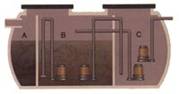
Flow enters the Solids Retention Section (A) that is separated by non-corrosive screen. Inorganic solids are retained behind the screen. Organic solids are broken by turbulence created with mixed liquor being forced through screen by submersible aeration pumps. This eliminates the need for mechanical comminution.
AERATION
Liquid and small organic solids pass through the screen into the continuing Aeration Section (B). Air and mixing are provided by submersible pumps with venture aspirators that receive air through pipe intake from the atmosphere.

DENITRIFICATION (OPTIONAL)
Provided by an anoxic period during the regular treatment cycle. Cromaglass units create anoxic conditions by closing the air intakes of the aeration pumps with electric valves. This stops aeration, but the system continues mixing.
TRANSFER/SETTLE
Treated mixed liquor is transferred by pumping to the Clarification Section (C). The transfer period overfills the Clarifier with the excess spilling through over-flow weirs back into the main Aeration Section. Transfer ceases and Clarifier ( C ) is isolated – solids separation occurs under quiescent conditions.
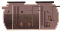
DISCHARGE
After settling, effluent is pumped out of the Clarifier ( C ) for discharge. Return sludge is pumped from the bottom of the Clarifier ( C ) back into the main Aeration Section (B) using a submersible pump or sludge can be wasted to a Sludge Processing Tank.